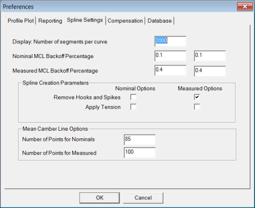
Use the Spline Settings tab to specify advanced settings for spline generation.

Preferences dialog box - Spline Settings tab
Display: Number of segments per curve box - Specifies the number of segments that make up the displayed curve. Enter a number between 50 and 2000.
If your plots look "blocky," then it may be useful to increase the Display: Number of segments per curve value to a higher value. This may slow down PC-DMIS Blade, but it increases the curved look to the section.
Nominal MCL Backoff Percentage and Measured MCL Backoff Percentage boxes - PC-DMIS Blade uses these percentages when the nose and tail points are computed. These points are found by intersecting the nominal or measured curve with the ray defined by the end of the mean camber line (MCL).
Often, the end of the MCL is not well-behaved. Set these percentages to define the amount that the point on the MCL should be backed away from the end. The value is a percentage of the MCL length.
For example, if the nominal chord length of a blade is 20, and you use the default percentage of 0.1, the point on the MCL that defines the location and direction of the terminal MCL ray is 0.02 from the end of the MCL. The units used are the spline parameterization.
If you are using the new MCL algorithm, PC-DMIS Blade ignores the Nominal MCL Backoff Percentage and Measured MCL Backoff Percentage percentages.
Spline Creation Parameters Area
Usually, it is not necessary to change these parameters for most inspections. Typical reasons for changes may include:
Remove Hooks and Spikes check box - For example, if you have rough or choppy nominal data, select the Remove Hooks and Spikes check box under Nominal Options. If the actual rough data that is being removed by Remove Hooks and Spikes, then clear this check box under Measured Options. Typically, this selection is used when measured splines are created as the data tends to less well-behaved, particularly after probe compensation. Usually, nominal data is well-defined and does not need this option.
Apply Tension check box - Modifies the computed spline slightly by applying tension. This results in a spline that is closer to the polygon that would be created by joining the points.
Mean Camber Line Options Area
The MCL is created by computing a set of points that satisfy the requirements for fitting on the MCL. That set of points creates the MCL spline curve.
Number of Points for Nominals box - Approximate number of points to use when you generate an MCL from the nominal curve.
Number of Points for Measured box - Approximate number of points to use when you generate an MCL from the measured curve.
More: