(This item pertains to the Analysis window, accessible from the View Window button on the Analysis dialog box. To open the Analysis dialog box, choose Insert | Report Command | Analysis.)
This Graphical Analysis dialog box determines the information that gets displayed in the Analysis window.
Graphical Analysis dialog box
To access this dialog box:
Select Insert | Report Command | Analysis from the menu to show the Analysis dialog box.
From the Analysis dialog box, from the Dimension list box, select the dimension.
Click View Window to show the Analysis window.
From the Analysis window's menu, select Options | Dimension Options to show the Graphical Analysis dialog box.
The dialog box contains two tabs:
An Analysis Options tab - For a description of the items on this tab, see "Analysis Options tab" below.
A Display Options tab - For a description of the items on this tab, see the "AnalysisWindow Object" topic in the "Reporting Measurement Results" chapter where it covers the Reporting Options tab.
Show arrow heads - This shows arrow heads on the deviation lines.
Show lines between measured hits - This shows lines between the measured hits.
Show lines between nominals - This draws lines drawn between the nominal values.
Show tolerance lines - This displays the acceptable tolerances for the dimension.
Show max/min deviations - This allows the maximum and minimum deviations to be indicated with a *+ or *- symbol.
Show grid - This displays a 3D grid-like backdrop for the graphical analysis. Enabling the grid may help you better visualize rotated items. It also enables the Grid Options button.
Grid Options - This displays the Analysis Grid Options dialog box. You can use this dialog box to define your grid.
Analysis Grid Options dialog box
The dialog box contains these options:
Automatically Size - This automatically sizes the grid based on the number of objects specified in the X, Y, and Z fields.
Specified Size - This enables the Maximum Boundary and Minimum Boundary boxes, which let you type specific sizes for the maximum and minimum boundaries.
Number of Elements - This defines the number of divisions that will be drawn on the analysis grid.
Maximum Boundary - This defines upper limits of the analysis grid coordinates.
Minimum Boundary - This defines the lower limits of the analysis grid coordinates.
Multiplier - This lets you type a scaling factor that magnifies the deviation arrows and tolerance zone for the graphical analysis mode. If a value of 2.0 is entered, PC-DMIS will scale the arrows two times the calculated deviation for each feature hit.
This option is used for viewing purposes only and is not reflected in the text-only printout.
Show Diameters - This shows the diameters of the available Position dimensions.
Show Best Fit Diameter, Max Inscribed Diameter, Min Circumscribed Diameter - These check boxes show the diameters for the Circularity dimension. These diameters represent the average, maximum, and minimum deviations for a round feature.
Show Contour Plot - This option only works for Profile dimensions applied to patch scans. The contour plot uses the patch scan's points to create a mesh. It then shades the mesh with the colors related to the profile deviations from each hit.
PC-DMIS can also display the contour plot on the CAD model in the Graphic Display window itself. For information, see "Displaying Surface Profile Contour Plots" in the "Using Legacy Dimensions" chapter.
Show Color Interpolation Between Hits - This inserts colors between hits. This option is available for Profile dimensions.
Show Arrows - This shows arrows for each point's deviation. This option is available for Profile dimensions.
Arrow Density - This slider changes the density of arrows for the points displayed in any dimension in the entire measurement routine that uses Graphical Analysis.
This differs from the Arrow Density functionality in the Reporting tab of the XactMeasure GD&T dialog box. The setting in the Reporting tab only affects that specific dimension. See "Reporting Tab" in the "Using Geometric Tolerances" chapter.
Worst - This box defines the number of worst deviations for which to display arrows. The following examples show all arrows on the left and the three worst arrows on the right:
Best - This box defines the number of best deviations for which to display arrows.
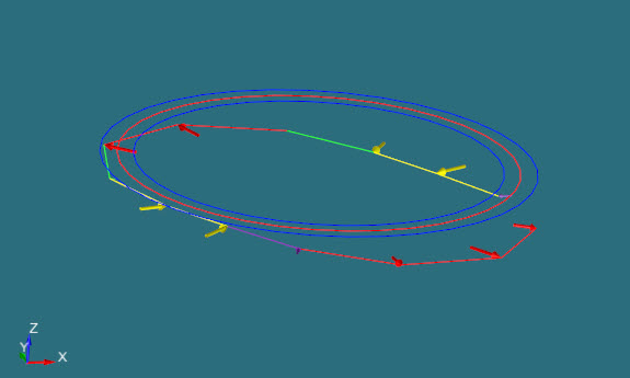
Example of All The Deviations (100% arrow density)

Example of 3 Worst Deviations