In this Topic Hide
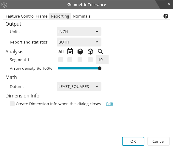
The Reporting tab of the Geometric Tolerance dialog box has several options to control how PC-DMIS evaluates and reports the calculations. The Reporting tab looks like this:
The Output area of the Reporting tab has these two drop-down lists:
Units - This allows you to report results in either inches or mm, regardless of the dimensions of your part program.
Report and statistics - This allows you to send the results to the REPORT, to the STATS, to BOTH, or to NONE.
The Analysis area of the Reporting tab allows you to control the textual and graphical analysis options. There is a row of check boxes for each segment of the geometric tolerance command. For example, with two segments the Analysis area looks like this:
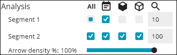
The icon above each column of check boxes is a label for which kind of analysis that column of check boxes controls:
 - Selecting
or clearing it selects or deselects the entire row of check boxes.
- Selecting
or clearing it selects or deselects the entire row of check boxes.
 - This
turns textual analysis on or off. You can hover your pointer over the
icon to see a tooltip that it is for report textual analysis.
- This
turns textual analysis on or off. You can hover your pointer over the
icon to see a tooltip that it is for report textual analysis.
 - This
turns CAD graphical analysis on or off. You can hover your pointer over
the icon to see a tooltip that it is for CAD graphical analysis.
- This
turns CAD graphical analysis on or off. You can hover your pointer over
the icon to see a tooltip that it is for CAD graphical analysis.
 - This
turns the report graphical analysis on and off. You can hover your pointer
over the icon to see a tooltip that it is for report graphical analysis.
- This
turns the report graphical analysis on and off. You can hover your pointer
over the icon to see a tooltip that it is for report graphical analysis.
The numeric values under the  icon are the arrow multipliers for each segment.
Underneath all of the segment analysis check boxes, there is a slider bar for the arrow density.
The Math area of the Reporting tab allows you to control the math options for evaluating the geometric tolerance. The Math area might look something like this:
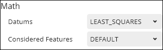
The Datums list controls the datum math. It is available when one or more datum features have surface data. For information on the math options and what they do, see "How PC-DMIS Solves and Uses Datums".
The Considered Features list controls the math to solve size tolerances and/or create the toleranced feature from the considered feature. It is available when the considered features have surface data and either (a) there is a size tolerance or (b) the toleranced feature is different than the considered feature. For details of what the options mean, see "Deriving the Toleranced Feature" and "Evaluating Size with the Geometric Tolerance Command".
The Tolerance Zone list (not pictured) controls the math for optimizing the toleranced feature into the tolerance zone. It appears for form tolerances and for profile tolerances without a datum. for details of the options' meaning, see these topics:
The Size area of the Reporting tab lets you control whether to report local sizes. It can look like this:

The Local Size option is either ON or OFF. It is available for considered features that have surface data, when there is a size tolerance. For more information, see "Evaluating Size with the Geometric Tolerance Command".
The Dimension Info area of the Reporting tab looks like this:

If you mark the check box, PC-DMIS inserts a dimension info command into your measurement routine after the geometric tolerance command. You can click Edit to the right of the check box to modify the dimension info command options.