 on the Tracker Measure
toolbar.
on the Tracker Measure
toolbar.You perform an Area Scan from the Area
Scan dialog box. To open the dialog box, select Insert
| Scan | Area Scan or click the Area Scan
button on the Tracker Measure
toolbar.
![]()
Tracker Measure toolbar
The Area Scan is only available for the ATS600 Tracker when you are online and a surface probe is your active probe.
You can use the settings on the Area Scan dialog box to open the Overview Camera window and define the scan region and scan settings. The software stores the region and settings you select so you can re-execute the scan. Since PC-DMIS stores the data in a pointcloud (COP), you must have a valid Reference COP ID defined in your measurement routine to create an Area Scan.
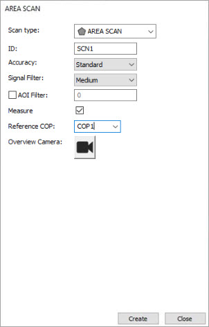
Area Scan dialog box
The Area Scan dialog box has these options:
Scan type - This list allows you to select one of the available scan types.
ID - This box displays the current scan identification text. You can edit it to a unique alphanumeric text name.
Accuracy - This list allows you to select one of the three scan accuracy options. The options are:
Standard - This option is useful in controlled environments to provide standard measurement accuracies.
Fast - This option is useful for applications when you need measurements as fast as possible.
Precise - This option provides the highest measurement accuracies but requires longer measurement periods.
Signal Filter - This list was called the Quality Filter prior to PC-DMIS 2020.2 and was found on the Surface Probe tab of the Machine Options dialog box.
Select an option from the Signal Filter list to filter and remove measured points that were measured when the laser beam was partially on and partially off the part surface. PC-DMIS filters the points in real-time while it scans.

Example using the Signal Filter setting to None (left) and Medium (right)
AOI Filter check box and input box - This is the angle of incidence filter setting. Click the check box to enable this filter, or un-check it to disable it. When you enable this filter, enter a valid value to define the maximum angle of incidence between the laser beam and the object's surface. The LeicaLMF interface software rejects any measured point that exceeds this value. The valid range for this filter is 0 (zero) - 90 degrees inclusive.
Measure check box - This check box enables you to set up a series of scans that you can insert into the Edit window and measure later. If you select the Measure check box and click the Create button, PC-DMIS starts to measure the scan immediately. If you do not select the Measure check box when you click Create, PC-DMIS inserts a scan object into the Edit window that you can measure later.
This check box is available only when PC-DMIS is Online.
Reference COP - This is the COP that PC-DMIS stores the scanned data in. If you don't select a COP from the list or enter one that is not yet created, PC-DMIS displays a prompt to ask if you want to create a new COP.
Overview Camera button - Click this button to display the Overview Camera window. For details on this window and its functions, consult the appropriate Leica manual.
More: