
The Quick Start interface contains a toolbar attached to the Quick Start dialog box (View | Other Windows | Quick Start). Many of the procedures on this toolbar use the Quick Start dialog box to perform their operations. The toolbar icons are discussed in the "Using the Quick Start Interface" topic.
This topic focuses on describing the items on the dialog box portion of the interface and how to use the dialog box to perform various operations.
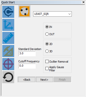
Sample Quick Start Interface
For all operations that use the Quick Start dialog box, PC-DMIS displays two icons at the top of the dialog box. A current procedure on the left and the current step in that procedure, or the current guessed feature, on the right.
If you see an asterisk icon, that means PC-DMIS is in a Guess mode operation.
For example, in the above
image, the Point icon on the right shows that with a single hit, a point
feature gets created. The icon on the right changes to a line if you take
another hit. PC-DMIS returns to this mode whenever you finish creating
a Constructed feature
or Alignment using the Quick Start dialog box. Click the Guess
Mode  icon
from the Quick
Start: Measure toolbar to place PC-DMIS in Guess mode.
icon
from the Quick
Start: Measure toolbar to place PC-DMIS in Guess mode.
Depending on the number of points taken, this mode guesses the feature type you’re attempting to measure and dynamically updates the Quick Start dialog box to reflect this. For example:
If you are in Guess Mode and you take two points, the Quick Start dialog box updates to a Line feature.
If you take four points, it updates to a Circle feature.
If you take eight points, it updates to a Cylinder, and so on.
See "Guessing a Measured Feature Type" in the "Creating Measured Features" chapter.
You can use this check box to create a measured feature with a single click of the mouse on the CAD model.
See "Creating Quick Start Measured Features" for information.
The unique ID for the feature. An ID appears in the box once you select an appropriate procedure.
See "ID" in the "Navigating the User Interface" chapter.
See "Editing Values and IDs" in the "Using the Edit Window" chapter.
This list is used to override the guessed feature measurement to the selected feature type. For example, if you take four hits and PC-DMIS guesses a plane, you can select Circle from this list to force it to create a measured circle instead.
See "Overriding a Guessed Measured Feature" in the "Creating Measured Features" chapter.
5, 6, 7, 8 - Reference Feature
You can project some measured features (circles, ellipses, lines, polygons, and slots) relative to a reference plane. The Reference Feature area appears in the Quick Start dialog box for these feature types where you can determine whether or not the measured feature is 3D, projected relative to the current workplane, or another user-defined plane.
You can select one of these types of reference features from the Type list (5):
3D - The measured feature is created in 3D space directly from the hits probed on the part. It is not constrained to fit relative to a plane.
For measured lines, the 3D item is not available because there is no way for PC-DMIS to know which way to compensate them.
Workplane - The measured feature is created as a 2D feature that is snapped onto a plane parallel to the referenced workplane and located at the average distance between the points.
Feature
- The measured feature is created as a 2D feature that is snapped
onto a referenced user-defined plane.
If you want the feature created at the average distance between the
points on a plane parallel to the referenced user-defined plane, you
must clear the Move Feature to Reference Plane
check box in the list of check boxes on the General
tab of the Setup Options dialog box.
See "Setup
Options: General Tab" for more information.
![]() If you need a reference plane feature that doesn't
exist in the Name list (6), click the plane
icon (7). The Quick Start dialog box walks
you through the process of measuring the plane feature and then returns
to the current line, circle, or slot measurement.
If you need a reference plane feature that doesn't
exist in the Name list (6), click the plane
icon (7). The Quick Start dialog box walks
you through the process of measuring the plane feature and then returns
to the current line, circle, or slot measurement.
Repeat - This functionality ties into the plane icon discussed in the previous paragraph. In some instances, you may want to create a new reference plane for each feature. Rather than clicking the plane icon before each feature measurement, you can mark this check box to have PC-DMIS repeat the plane creation sequence before measuring each feature. PC-DMIS prompts you to take three hits to create the reference plane first. When you click Finish, it then prompts you to take the hits for the actual feature.
You can use the Move Feature to Reference Plane check box on the General tab of the Set Up Options dialog box to have 2D features snapped directly onto the reference plane instead of onto a parallel plane.
9 - Number of Hits Taken / Required Hits
This display shows two numbers.
The number on the left of the slash indicates the number of hits you have currently taken.
The number on the right of the slash indicates the minimum hits you need to measure the feature. You can take more than the minimum number of hits, in which case, the number to the left of the slash will be greater than the number on the right. You can also increase the number to a user-defined minimum.
The up arrow increases the feature's defined minimum number of hits (the number on the right of the slash) by one.
The down arrow decreases the feature's defined minimum number of hits (the number on the right of the slash) by one.
The Store a Move icon is used to easily store move points into the measurement routine. When you click this icon, PC-DMIS reads the current location of the probe and inserts a MOVE/POINT command into the Edit window.
See "Inserting a Move Point Command" in the "Inserting Move Commands" chapter.
The Remove a Hit icon removes the last hit from the hit buffer.
You can use the Auto
End check box to have the software automatically finish or end
a feature in learn mode once it detects that you have taken the required
number of hits. This means you don't need to press a key or click a button
to learn the feature. You can use the Increase Hits
or Decrease Hits arrow buttons to set the required
number of hits. 
The Results box shows the results of all steps in a measurement procedure taken thus far. For example, if you want to do a Plane - Line - Line alignment, the results box shows the following when you select or measure the second line:
Step
1:PLN1=Measured Plane
Step 2:LIN1=Measured Line
Step 3:LIN2=Measured Line
The Results box is tied to the buttons at the bottom of the dialog box. The buttons become enabled whenever you fulfill the requirements for a certain step in a procedure.
The <Back and Next> buttons cycle between lists of the required features or inputs. These buttons become available when procedures used on the toolbars require the selection or creation of multiple features (such as the Dimension and Align toolbars) or user input (such as upper and lower tolerance values for dimensions).
Clicking the Done button on your jog box acts the same as clicking the Next> button when using the Quick Start dialog box.
The Finish button completes the procedure, inserts the appropriate command into the Edit window, and then, in most cases, PC-DMIS returns to the initial step of the current procedure. For alignments or constructed features, however, after you click Finish, PC-DMIS returns to the default Guess Mode.
Constructed Features Interface
For some constructed features, when working through the steps to create the features, the Quick Start interface displays additional options with a green background, similar to this:
These options are not described in this chapter. For information on these options, consult the appropriate topic in the "Constructing New Features from Existing Features" chapter.

