(This item pertains to the Custom Probe Builder Utility, accessible through Edit | Preferences | Custom Probe Builder Utility.)
Creating Connection Points
Connection points are used to define the faces to be used to attach components to when building an assembly. This allows more control over your assembly.
To create connection points on a Polygon element:
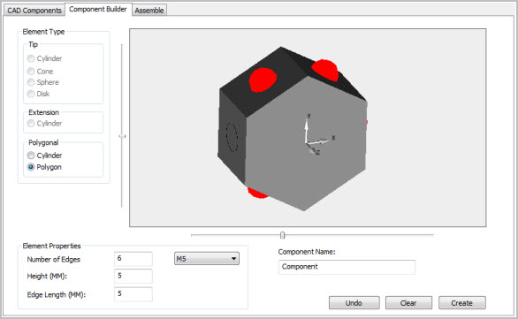
Select the Polygon option from the Polygonal section of the Component Builder tab.
Adjust the Element Properties as needed.
The Number of Edges box accepts a minimum value of 3 and a maximum value of 20. If you enter a value less than 3, the box is reset to 3; if you enter a value greater than 20, the box is reset to 20.
Enter a unique name for your component in the Component name section then click Create.
Custom Probe Builder Utility - Component Builder tab showing a polygon and its default connection points
A basic polygon is displayed with red connection dots. The red connection dots are displayed on five of the sides. Each dot represents a connection point that can be used in an assembly.
To manage which connection points are available for a particular assembly, click any of the connection point dots to disable or enable. In the image below, the front (left side) face connection is disabled. Clicking a disabled point re-enables it.
Custom Probe Builder Utility - Component Builder view of a connection point disabled
When all the properties and connection points have been defined, click Save. If this is a new component, enter a name in the Component Name field and then click Save.
Using Connection Points
Once the changes in the Component Builder tab have been saved, they can be used to assemble a custom probe.
To assemble a custom probe using the built component:
Click the Assemble tab.
In the Probe File section, click the file name used to saved your changes.
Click the type of connection from the Connection Type list. The components in the Component Selection list updates based on the type of connection selected. Only items that connect to this connection type are listed.
The component assembly is detailed in the Assembled Components section. Click the connection you want to begin building on in the Assembled Components tree. The first "empty" connection is always selected by default and is highlighted. If the selected connection face is empty, it shows the red connection dot. Rotate the image if you can't initially see it.
Select a component from the Component Selection list.
The selected connection in the Assembled Components section is the face that is updated when you begin building your assembly. To work on another face, click a different connection in the Assembled Components section. The selected face is updated with the red connection dot to signify it is the face the next selected component is built onto.
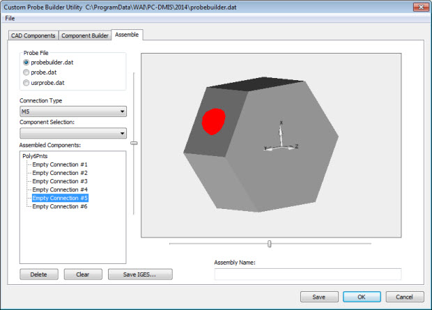
Custom Probe Builder Utility - Assemble tab showing a polygon and the Connection #5 connection point
A face that already has a component connected to it can be replaced with a new component:
Click the component to be replaced in the Assembled Components tree.
Select a new component from the Component Selection list to replace it.
Remove a component from a connection point without replacing it:
Click the component in the tree to be deleted.
Click Delete.
Once you've selected the face to work on, click the next component from the Component Selection list. The selected item is automatically attached to the targeted face - the face with the red connection dot on it.
Repeat as needed until your assembly is complete.
When finished, type a name for your assembly in the Assembly Name box.
Save the changes:
Click Save IGES to save the assembly as an IGES file.
Click Save to save the assembly into the .dat file created or opened in the current session
More:
Custom Probe Builder Utility Dialog Box
Custom Probe Builder Utility File Menu
Custom Probe Builder Utility CAD Components Tab