(This item pertains to the Custom Probe Builder Utility, accessible through Edit | Preferences | Custom Probe Builder Utility.)
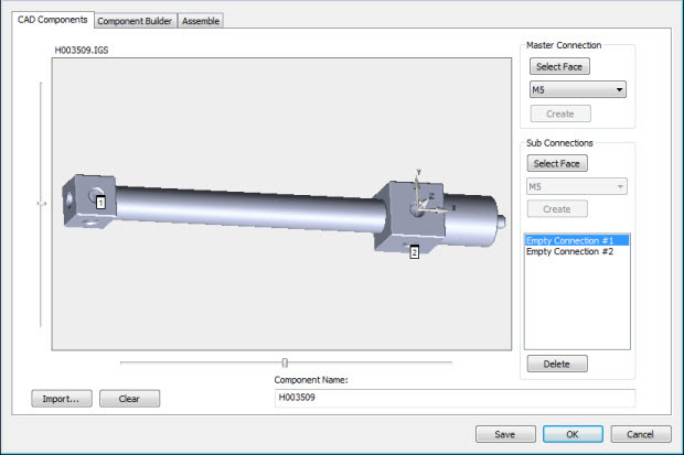
Custom Probe Builder Utility - CAD Components tab
The options available on the dialog box are:
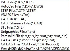
Click Import to import most of the formats PC-DMIS allows from the local or network drive location into the measurement routine. These are the allowed file types.
Click Clear to clear any unsaved work and start work on another item.
Click Save to save any changes to the defined custom probe .dat file. The dialog box remains open if you need to make additional edits.
Click OK or Cancel to close the dialog box. The application does not automatically save your changes. Make sure you click Save prior to clicking OK or Cancel.
Defining the Master Connection
The Master Connection defines the main connection point of a component once you add it to an assembly. It also serves to define the alignment of the assembly. Left-click a surface or feature on the CAD model to create the master connection points.
To configure a master connection type:
Click Import to open a CAD file. Once it imports, you can interact with the model and define connection points for other probe components.
If you opened a file with all your connection points defined, click the Component Builder tab to build custom probe components.
You can zoom and rotate the image in the dialog box's graphic area similar to the PC-DMIS Graphic Display window. For example, you can press Ctrl + Z to re-draw the image to fit entirely within the graphics area. Use the sliders along the bottom and left of the graphic area to manipulate the CAD model.
Click the Select Face button from the Master Connection section to place the dialog box into a selection mode. The dialog box remains in this mode until you click the Select Face button again or you define a master connection.
From the list in the Master Connection area, select a connection type.
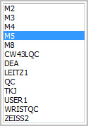
Custom Probe Builder Utility - CAD Components tab Master Connection Types menu
Click the surface or feature for the master connection. The software highlights the selected surface.
Click Create to finalize the master connection. The alignment updates to the selected feature with the Z axis perpendicular to it.
Defining Sub Connections
You can connect other components to sub connections to create an assembly. The Master Connection of one component connects to the selected sub connection of another component. For details on creating assemblies, see the topic "Custom Probe Builder Utility - Assemble Tab".
To define sub connections:
Click the Select Face button from the Sub Connections section to place the dialog box into a selection mode. The dialog box remains in this mode until you click the Select Face button again.
Select a connection type from the list in the Sub Connection area.
Click the surface or feature for the sub connection. The software highlights the selected surface.
Click Create to finalize the sub connection. Once you create the sub connection, the Create button is disabled until you select another feature. Create as many sub connections as needed. As you create sub connections, they appear in the lower list box as "Empty Connection #1", "Empty Connection #2", and so forth.

Custom Probe Builder Utility - Sub Connections section
When you click Create, the software disables the lower connection type list box.
You can delete connections. Select one or more connections, then click Delete.
Once you have defined all master and sub connections, in the Component Name box, enter a name for the new component, then click Save. The dialog box remains open so you can build components from the Components Build tab or probe assemblies from the Assemble tab.
Click OK to exit the utility or click Cancel to exit the utility.
Custom Probe File Format
The software saves your custom probe configuration as a .dat file. This uses the same format as the probe.dat file.
ITEM:5H003512 M5
cadgeom 0.000 0.000 0.000 1.000 0.000 0.000 0.000 1.000 0.000 0.000 0.000 1.000 -1 5 H003512.draw
connect -1.108 -27.715 -113.565 0.508 0.759 0.408 M5
connect 2.859 33.883 -112.237 0.479 -0.789 -0.384 M5
More:
Custom Probe Builder Utility Dialog Box
Custom Probe Builder Utility File Menu
Custom Probe Builder Utility Component Builder Tab