For details on extracting Auto features from a Mesh, see the "Extracting Auto Features from a Mesh" topic in the PC-DMIS Laser documentation.
For details on extracting Auto features from a Pointcloud (COP), see the "Extracting Auto Features from Pointclouds" topic in the PC-DMIS Laser documentation.
You can construct a plane that is extracted from a scanned Pointcloud (COP) or Mesh.
To do this:
Ensure that your measurement routine has a Pointcloud (COP) or Mesh command.
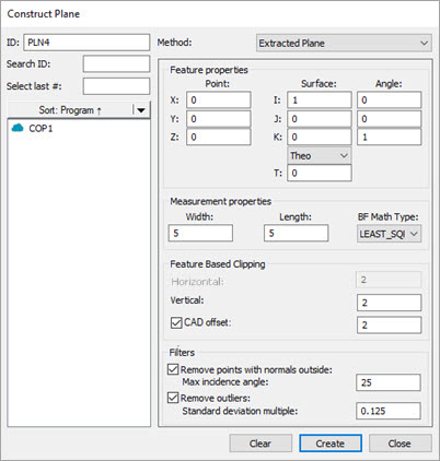
Open the Construct Plane dialog box (Insert | Feature | Constructed | Plane) or from the Constructed Feature toolbar (View | Toolbars | Constructed Features).
Construct Plane dialog box - Extracted Plane
From the Method list, select the Extracted Plane option.
From the Reference area, select the COP or Mesh that you want to use to extract the plane from.
Click on the CAD model or data to define the nominal or, in the Point section of the Feature properties area, type the nominal location in the X, Y, and Z boxes.
From the Surface section of the Feature properties area, define the surface vector in the I, J, and K boxes. You can use the Material Thickness Type list and the T box below it to define the material thickness value. For details, see the "Use Thickness" topic in this documentation.
In the Measurement properties area, type the properties for the plane in the Width and Length boxes. Also, select the type of Best Fit algorithm to use to construct the plane from the BF Math Type list. For details on the algorithm types, see the "Best Fit Type (for Plane)" topic in this documentation.
PC-DMIS draws the extraction zone and centers it around the XYZ location point. This box defines the zone that PC-DMIS uses for the extracted plane.
The black outline is the surface.
The green boundary represents the horizontal and vertical boundary zones.
The orange points are the candidate points that the extraction considers.
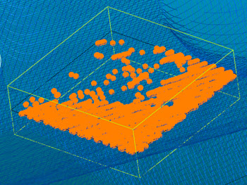
Example of an Extracted Plane showing the candidate points
From the Feature Based Clipping area, define the Horizontal and Vertical values. This sets the dimensions for the extraction zone region. Consider part variability when you define the extraction zone.
Alternatively, you can clip data within an offset boundary around all the CAD elements on a surface with the CAD offset option. This is also called CAD segregation. For details, see the "CAD offset" section of the "Feature Based Clipping Parameters" topic in the PC-DMIS Laser documentation.
If you want to filter out any points that are outside of a maximum incidence angle, from the Filters area, select the Remove points with normals outside check box and type the value in the Max incidence angle box.
If you want to filter out any outlier points, from the Filters area, select the Remove outliers check box and define the Standard deviation multiple to determine which points PC-DMIS excludes as outliers.
Click the Create button. Based on the parameters that you specified in the dialog box, PC-DMIS does an analysis of the candidate points, and returns (or extracts) the plane and projects it to the surface.
PC-DMIS creates the command in the Edit window:
PLN3=FEAT/POINT,CARTESIAN,LEAST_SQR
THEO/<73.598,33.658,0>,<0,0,1>,<1,0,0>
ACTL/<74.116,36.299,0.001>,<-0.0004985,0.0007789,0.9999996>
WIDTH=5,LENGTH=5,
THEO_THICKNESS,0,
HORIZONTAL CLIPPING=3,VERTICAL CLIPPING=2,
USE OUTLIER REMOVAL=ON,0.125,
REMOVE POINTS WITH NORMALS OUTSIDE=ON,25,
CONSTR/PLANE,EXTRACTED_PLANE,REF=COP1