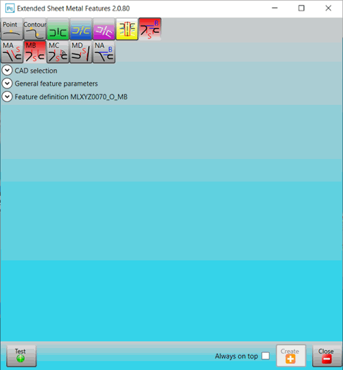
To create an ESF command, follow these steps:
Select Insert | Modules | ESF. (This option is available after your portlock or LMS license has been configured with the appropriate option and the ESF toolkit module has been installed.) The Extended Sheet Metal Features dialog box appears.

Extended Sheet Metal Features dialog box
Select a measuring principle. When you select it, its icon turns red and its features appear.
These are the measuring principles. The feature for each principle appear beneath the selected principle:
Point:
![]()
Contour:
![]()
Hole (in a planar surface punched normal to the surface):
![]()
Hole (in a planar surface punched not normal to the surface):
![]()
Hole (in a curved surface):
![]()
These are the options when the Use2018NamingConvention check box is not selected
![]()
These are the options when the Use2018NamingConvention check box is selected
For details on the Use2018NamingConvention check box, see the "Global Application Settings Dialog Box" topic.
Standard Part:
![]()
Flush or Gap
![]()
Select the feature that you want to create, and then complete its options. For details, refer to the appropriate documentation:
Creating a Hole feature in a punched planar surface:
To keep the Extended Sheet Metal Features dialog box on top of the other windows on your computer, regardless of whether the dialog box is active, select the Always on top check box. To keep the dialog box underneath windows that are new or in focus on your computer, clear the check box.
To test a feature's creation and preview its dimensional data before it is actually created, click Test. PC-DMIS performs a measurement using the current parameters. You can change parameters and click Test repeatedly until you have an acceptable measurement. Then when you click Create, the software converts the temporary feature into a normal feature in the measurement routine.
When you click Test, the Execution dialog box appears. For help on how to use this dialog box, refer to "Using the Execution Dialog Box" in the "Using Advanced File Options" chapter in the PC-DMIS Core documentation.
To create the feature after you complete its options, click Create. The Extended Sheet Metal Features dialog box remains open.
To close the Extended Sheet Metal Features dialog box, click Close.
More: