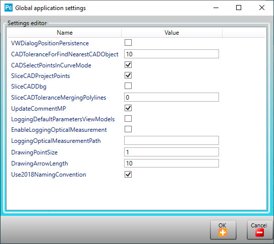
Global application settings dialog box
You can use the Global application settings dialog box to set ESF parameters. To open, right-click anywhere in the title area of any ESF dialog box.
The available parameters are:
VWDialogPositionPersistance - Select this check box to save the dialog box's location on the screen when it's closed. The next time you open the dialog box, it opens in the same screen location.
CADToleranceForFindNearestCADObject - This box sets the tolerance value in mm that PC-DMIS uses when it searches for the nearest CAD object from the selected CAD object in the Graphic Display window.
CADSelectPointsInCurveMode - Select this check box if you want PC-DMIS to select points in Curve mode.
SliceCADProjectPoints - Select this check box if you want to project all the points that are part of the polyline onto the section plane. A Contour feature is a good example, where PC-DMIS slices the CAD model to create the section.
SliceCADDbg - Select this check box if you want PC-DMIS to draw all the points on the CAD model that were used to create the slice. This only applies to Contour features.
SliceCADToleranceMergingPolylines - Use this box to set the correct tolerance value to resolve a common issue with CAD files, where two adjacent surfaces do not connect. When this occurs, an empty space between the two surfaces results and the CAD engine fails to slice the curve when you program ESF features.
UpdateCommentMP - Select this check box to add another line that contains the feature's name to the Dimension comment.
LoggingDefaultParametersViewModels - Select this check box to store the default parameters in the log file located here: C:\Users\<UserName>\AppData\Local\Temp\ESFDefaultParametersViewModels.log.
EnableLoggingOpticalMeasurement - Select this check box to store feature extraction log files in the folder specified in LoggingOpticalMeasurementPath.
Be aware that ESF logging is quite extensive and creates huge datasets for each single execution of each single ESF feature which slows down the execution of the measurement routine.
You should only turn logging on when you need log files to investigate a suspected issue. Once done, you should immediately turn logging off.
LoggingOpticalMeasurementPath - This box defines the complete path location to where PC-DMIS saves the extraction log files.
DrawingPointSize - This box defines the dimension in mm of the point objects in the Graphic Display window.
DrawingArrowLength - This box defines the dimension in mm of the arrow objects in the Graphic Display window.
Use2018NamingConventions - This check box allows you to switch the naming convention between the 2014 and 2018 naming conventions. When you select this check box, PC-DMIS uses the 2018 naming convention for the Hole (in a curved surface) measurement principle features. Otherwise, PC-DMIS uses the 2014 naming convention.
More: