REFERENCE Method
The TIPARC method measures the edge thickness relative to the end point. The edge thickness is calculated at the intersection of a radius with the parameter of LE_OFFSET (or TE_OFFSET) and the mean camber line (MCL).
This method creates a circle of radius LE_OFFSET around the end point and intersects the circle with the MCL. This yields the MCL intersection point.
The TIPARC method uses the direction of the surface at the end point. Measured splines are sometimes a little wiggly, which can make the end-point direction unrepeatable from blade to blade. To make end-point directions more stable, you can define the parameters for the LE_FLAT_SIZE and TE_FLAT_SIZE keywords in the Tolerance file. The parameters specify the diameter of a circular zone that is centered on the end point. PC-DMIS Blade fits a least-squares line to everything inside the zone and defines the direction of that least-squares line to be the end-point direction used in the TIPARC method.
After the TIPARC method identifies the MCL intersection point, the NORMAL, SQUARE, XWIDTH, and YWIDTH calculation methods continue with the measurement as follows:
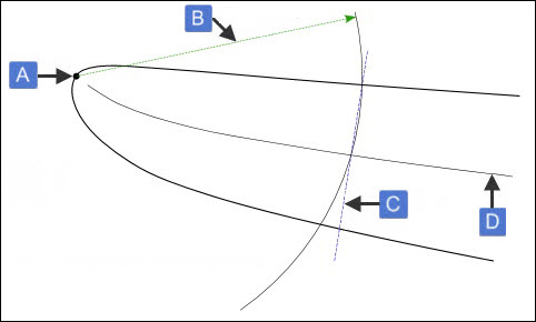
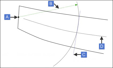
The NORMAL method measures the edge thickness perpendicularly to the MCL and through the MCL intersection point. For example:

Example of NORMAL and TIPARC methods with normal edge
A -Edge point
B - LE_OFFSET
C - Edge thickness perpendicular to MCL
D - MCL

Example of NORMAL and TIPARC methods with square edge
A -Edge point
B - LE_OFFSET
C - Edge thickness perpendicular to MCL
D -MCL
The XWIDTH and YWIDTH methods report the X-component and Y-component, respectively, of the edge thickness perpendicularly to the MCL.
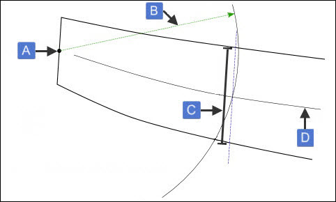
The SQUARE method measures the edge thickness through the MCL intersection point and parallel to the end point. For example:

Example of SQUARE and TIPARC methods
A -Edge point
B - LE_OFFSET
C - Edge thickness parallel to end point
D - MCL
The TIPARC method is available for the following calculations:
LETHCK
LETHCK2-10
TETHCK
TETHCK2-10
More:
MCL Calculation Method