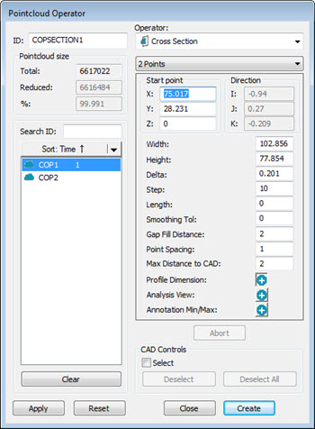
You can create a cross section between two points with the 2 Points function from the Pointcloud Operator or Mesh Operator dialog box.
Pointcloud Operator dialog box - CROSS SECTION Operator, 2 Points function selected
The 2 Points cross section is created between two selected points and is oriented normal to the current Graphic View. The cross section's purple Length line is perpendicular to the line defined by the two selected points. It is created at the midpoint of this line and defaults to 0 (zero).
To create a cross section between two points:
For cross sections created with a COP as the input, click Insert | Pointcloud | Operator to display the Pointcloud Operator dialog box.
For cross sections created with a Mesh as the input, click Insert | Mesh | Operator to display the Mesh Operator dialog box.
Select the Cross Section operator from the Operator list, and then select the 2 Points function from the list underneath the Operator list.
From the QuickMeasure or Graphic View toolbar, select the correct Graphic View for the cross section orientation. For details on the QuickMeasure toolbar, see "QuickMeasure Toolbar" in the PC-DMIS CMM documentation. For details on the Graphic View toolbar, see "Graphic View Toolbar" in the "Using Toolbars" section of the PC-DMIS Core documentation.
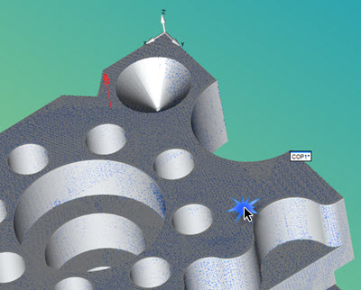
From the Graphic Display window, click where you want to define the cross sections's first point.

The point's vector appears as a red arrow normal to the selected surface.
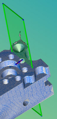
From the Graphic Display window, click where you want to define the cross sections's second point.
Once the second point is clicked, the cross section is displayed.
Adjust the cross section's properties as needed.
More:
Creating a Cross Section along a Curve
Show and Hide Cross Section Polylines