Distances can be measured on 2D cross sections in the Graphic Display window. You must already have the cross sections created and be in cross-section 2D view. For details on how to view cross sections in 2D view, see "Show and Hide Cross Section Polylines".
To create a cross-section Distance Gage:
From the Pointcloud, QuickCloud, or Mesh toolbar (View | Toolbars), click the Cross Section drop-down arrow to display the Cross Section toolbar.
Click the 2D Section Slide
Show button ( ) to enter 2D view.
Click the Show the previous 2D Section or Show the next 2D Section button until the cross section is displayed in the Graphic Display window.
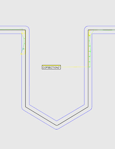
In the Graphic Display window, hover over the cross section, and then click and drag to display the start point.
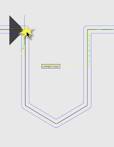
Drag the cursor to the end point, and click to select it. The Distance Gage is calculated, created, and displayed in the 2D view with its associated label.
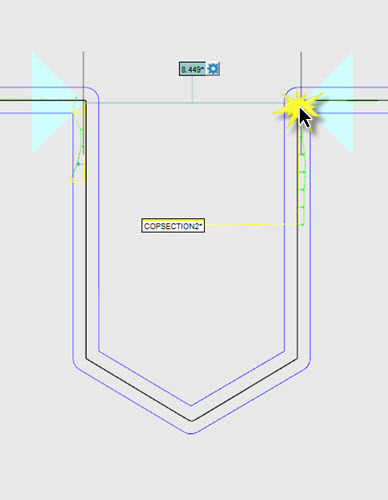
As you drag the cursor, the software intuitively detects if the start and end points are along an axis. If they are, the direction is recognized and constrained parallel to that axis.
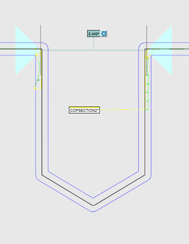
Parallel Distance Gage example
To create a Distance Gage parallel to the first side picked:
Press and hold the Shift key.
Click the start point, and drag and click the end point.
An example of this would be if the cross section was not created along the X, Y, or Z axis.
If the start and end points are offset from one side to another, the axis direction is still recognized. The distance, however, is calculated parallel but between the offset points.
Offset Distance Gage example
To change the properties of the Distance Gage,
click the Distance Gage Options button ( ) on
the label. The Distance Gage Options dialog
box appears.
) on
the label. The Distance Gage Options dialog
box appears.
For example, if you do not want the Distance Gage calculated as an offset calculation, select the Parallel option from the Constraint list. Click the start and end points as before; the Distance Gage is calculated between the two points.
Example of a Distance Gage calculated with the Parallel Constraint option selected
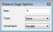
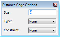
Edit the properties of the Distance Gage:
Size - If the None option is selected in the Type list, the Size value is used to determine the size of the start and end point icons in the Graphic Display window. If either the Best Fit, Max Fit, or Min Fit option is selected from the Type list, the Size value is used as described below. A size of 4 is the default.
Type - Click the drop-down arrow to display these options:
None (default) - A Point-to-Point distance calculation between the closest cross section polyline points based on the selected start and end points.
Best Fit - A Least Square line is calculated based on all the yellow points within the first pick zone, defined by the Size value (the default is 4) and the selected start point. This is repeated for the second pick zone, defined by the Size value and the selected end point. The centroid of the first Least Square line is projected onto the measurement zone line. This is repeated for the centroid of the second Least Square line. The distance is between these two projected points.
Max Fit - Defined by the point farthest out in the first pick zone, defined by the Size value and the selected start point, and by the point farthest out in the second pick zone, defined by the Size value and the selected end point. The Max Fit points are projected onto the measurement zone line. The Max distance is between these two projected points.
Min Fit - Defined by the closest point in the first pick zone, defined by the Size value and the selected start point, and in the second pick zone, defined by the Size value and the selected end point. The Min Fit points are projected onto the measurement zone line. The Min distance is between these two projected points.
If the Type option is changed, the measured distance is automatically recalculated, and the updated value is displayed based on the option selected.
Constraint - Select None (default) if you do not want to constrain it to any axis. Select the appropriate option to constrain the Distance Gage to the X, Y, or Z axis, or Parallel to calculate the distance parallel to the first selected side.
Creating a Distance Gage with and without Measured Points
You can create a distance gage with or without measured points on either side of the gage.
Example #1
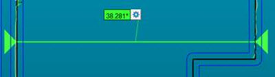
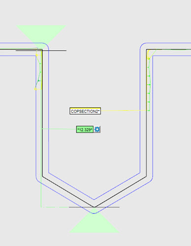
Distance Gage created using measured points on both sides (indicated by colored arrows)
Example #2
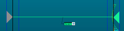
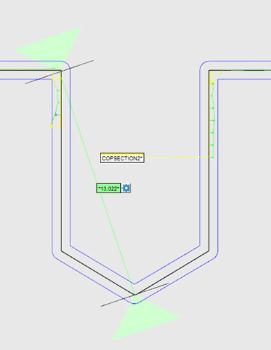
Distance Gage created using measured points only on one side
In this case, PC-DMIS precedes the distance value with an asterisk. This indicates that one or more sides are not measured. The value shows the distance between the nominal (gray arrow side) and the measured side.
Example #3
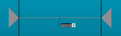
Distance Gage created with no measured points on either side (gray arrows)
In this case, the distance gage shows the nominal value.
Creating a 3D Distance Gage
To create a 3D Distance Gage that is not constrained to any axis:
Press and hold the Ctrl key, hover over the cross section in the Graphic Display window, and click and drag to display the start point.
Continue to drag the cursor with the Ctrl key pressed to the end point location.
Click to select the end point and display the Distance Gage and its associated label.
The same functionality is available as described earlier for 2D Distance Gages. Click the Distance Gage Options button to view the Distance Gage Options dialog box. The Constraint option is set to None.
More:
Creating a Cross Section along a Curve
Creating a Cross Section between 2 Points