This section describes how to define and calibrate the ACR1 Probe Changer.
No inserts are used for any of the port positions. However, if you intend to use probe extensions in any of the ports, you must define them as part of the port type before you begin.
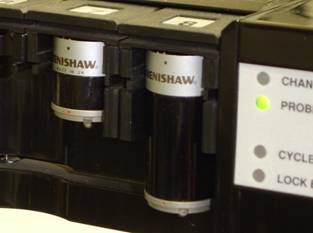
ACR1 Probe Changer that shows two different probe extensions, used here in ports 7 and 8
The ACR1 Probe Changer MUST BE mounted on the machine table parallel to either the X or Y axis for successful calibration. For mounting instructions, consult the documentation that came with your probe changer.
To calibrate your probe changer:
Step 1 - Select the ACR1 Probe Changer
Step 2 - Define the Communications Port
Step 3 - Define the Mount Point
Step 5 - Prepare for Calibration
Step 8 - Measure the Datum Sphere
Step 9 - Measure the Datum Sphere with PEM Extension(s) (optional)