In this Topic Hide
Concentricity Versus Coaxiality
Datums as Alignment Versus Datums as Gage
Example 1: plane | circle | circle datum reference frame
Example 2: plane | circle | width datum reference frame
Projected Tolerance Zones on non-Auto Cylinders
Datum Material Modifiers on Orientation Tolerances
Profile Tolerances with OPTIMIZED_FIT
Unusual Tolerance Zone Shapes on Spheres
Specified Material Boundary Size on ISO Datum
Axial Versus Radial Zones For Circular Runout
Symmetry and Concentricity under ASME
3D Best Fit (BF) Constructed Lines
3D Best Fit Recompensated (BFRE) Constructed Lines
Migration of Simultaneous Tolerances
Simultaneous Profile of a Line Tolerances Referencing a Workplane
PC-DMIS 2020.2 introduced the geometric tolerance command. This command replaces the XactMeasure command offered in prior versions. When you open a measurement routine from a version before PC-DMIS 2020.2, the XactMeasure tolerances no longer exist, and PC-DMIS attempts to migrate the FCF (Feature Control Frame) commands to the equivalent geometric tolerance command.
Prior to migration, when you open your routine in this
version of PC-DMIS, the software creates a backup of your measurement
routine in this folder:
C:\Users\Public\Documents\Hexagon\PC-DMIS\2020.2\MigrationBackup
Never open this routine from this backup location. If you want to use the
backed up routine, copy it to another folder first.
Migration is mostly automatic, but in some cases, you may need to customize the migration to your needs. You can use some options to control how the migration takes place. We suggest the following workflow to migrate your PC-DMIS measurement routines from a prior version:
Make sure the nominal values of all features in your measurement routines are correct.
Back up your old measurement routines to a safe place, and never open them with 2020.2 or later.
Make a copy of your backup measurement routines in a folder you are willing to experiment with.
Open the experimental copies of your measurement routines in this version of PC-DMIS.
Examine carefully the results of the migration. Verify that the migration worked as desired and that the new measured values fit your needs.
In rare cases, a migration might not work for you in a small number of places. In these cases, manually edit those places in your program to update the commands.
In rare cases, the migrated math types might not work for you in a large number of places. If this happens, adjust your migration options, make new copies from your backup measurement routines, and place the copies in the experimental folder. Then open these new copies with this version.
Repeat this workflow until all of your measurement routines are working for you.
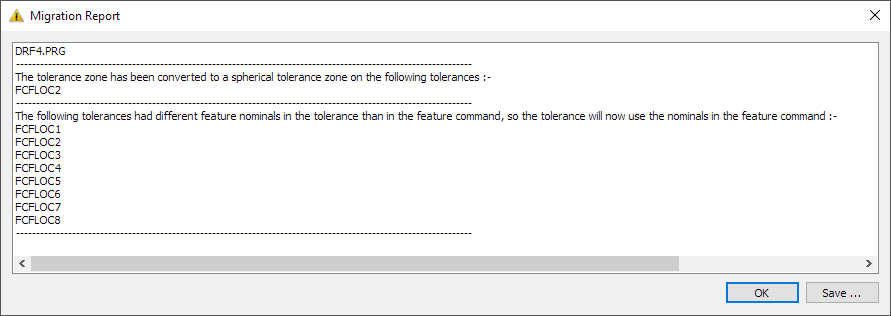
When PC-DMIS encounters issues during migration, the migration tool creates a report in a Migration Report dialog box. The migration report looks like this:
Most migration reports are much simpler than the example in the image above. In the image above, the report conveys two main pieces of information:
PC-DMIS changed a tolerance zone to a spherical tolerance zone. This is discussed below in "Unusual Tolerance Zone Shapes on Spheres".
PC-DMIS discarded multiple tolerances with customized nominals. This is discussed below in "Customized Nominals".
The geometric tolerance command behaves differently from the XactMeasure command in several ways. Some of those differences are particularly apparent during migration:
The XactMeasure command had separate dimensions for concentricity versus coaxiality, with separate visual symbols for each. This resulted in these problems:
ASME Y14.5 makes no distinction between concentricity and coaxiality. All such tolerances are concentricity.
ISO 1101 uses the same concentricity symbol for both concentricity and coaxiality.
The XactMeasure symbol for coaxiality was not in any standard.
The meaning of the concentricity symbol is clear for either ASME or ISO once you know the type of the considered feature. This means there is no need to have separate dimensions for concentricity and coaxiality.
Therefore, all XactMeasure coaxiality and concentricity dimensions are migrated to the geometric tolerance command using the concentricity symbol.
In some cases, the XactMeasure command allowed your considered features and/or datum features to have incorrect nominals. These were in perpendicularity, parallelism, symmetry, concentricity, coaxiality, circular runout, and total runout. These cases may be considered "implicit nominals" where the XactMeasure command assumed it knew the correct nominal relationship between the considered features and the datum features. The geometric tolerance command does not make this assumption. It requires all features to have correct nominals. After migration, if the features have bad nominals, and the geometric tolerance command can detect that you have bad nominals, the geometric tolerance command produces an error.
For example, suppose you have a perpendicularity tolerance, with a planar considered feature and a planar datum. The nominal angle between the considered plane and the datum plane is 89.3°. XactMeasure would assume that the nominal angle is really 90°, and it would produce a measured value with that assumption.
The geometric tolerance command requires all features to have correct nominals. That means it takes the 89.3° nominal angle at face value. The perpendicularity tolerance produces an error message after migration, stating that it does not make sense to have a perpendicularity tolerance on features that are not nominally perpendicular to each other.
That message means you need to decide whether the 89.3° nominal angle is correct or not:
If 89.3° is correct, and it matches the drawing (or CAD file), this means that the drawing (or CAD file) is wrong and needs to be corrected, because it does not make sense to have a perpendicularity tolerance on features that are not nominally perpendicular to each other.
If 89.3° is incorrect per the drawing (or CAD file), this means that the feature nominals are wrong, and you need to correct them.
For angularity and position, the XactMeasure command allowed you to customize the considered feature nominals. Angularity allowed you to type a nominal angle between the feature and the primary datum. Position allowed you to type the XYZ centroid of the feature and the nominal size of the feature. In retrospect, we never should have added that capability because it enabled users to have features with bad nominal values. The geometric tolerance command requires all features to have correct nominals, and it does not allow you to customize the feature nominals. After migration, PC-DMIS discards any customized nominal values, and it uses the feature nominals. If you have customized your feature nominals, we detect this during migration and show a warning message in the Migration Report.
The geometric tolerance command allows slot and notch datum features and interprets them as 2D width features without surface data. For more information, see "Datum_Slots_and_Notches". By contrast, the XactMeasure command treated slot and notch datum features like 2D circle features without surface data. This made it more difficult to use XactMeasure in a standards-compliant way.
When you migrate a routine with a slot or notch feature as a datum, the tolerance's measured value may change due to the change in how PC-DMIS interprets the datum feature.
Be careful with datum slots and notches.
You should only use them if you already know that the form of the features is very good. If you suspect that the manufactured form error might be significant, do not use a slot or notch command. Instead, measure a scan around the perimeter of the feature and then tolerance the form, orientation, and location of the feature with a profile of a line tolerance.
If you need to reference the feature as a datum, instead of a slot or notch, use a constructed 2D or 3D width (with surface data).
As discussed in "How PC-DMIS Solves and Uses Datums", the XactMeasure command used PC-DMIS alignment concepts to solve datum reference frames, such as level, rotate, and origin. By contrast, the geometric tolerance command uses gage concepts to solve datum reference frames. This allows PC-DMIS to solve unusual datum reference frames that do not fit into the level-rotate-origin framework. It also allows for easier standards compliance in cases where the level-rotate-origin framework is an imperfect match for the standards in question.
Sometimes you need to be aware of the differences in the results, so that you can understand why the XactMeasure command gave different results than the geometric tolerance command.
Here are some examples:
A frequently-seen datum reference frame is the primary datum plane, followed by a secondary datum circle, followed by a tertiary datum circle. Here's an illustration of the specification, where the primary datum plane is A, the secondary datum circle is D, and the tertiary datum circle is E:
XactMeasure levels to the primary datum plane first. It then sets the origin on the secondary datum circle. Finally, it rotates to the line between the secondary and tertiary circles. Here's an illustration of the XactMeasure behavior, using least squares math:

The geometric tolerance command with ASME and no datum modifiers gets a slightly different datum reference frame. The primary datum plane is fitted first. This yields a primary datum plane simulator and a planar invariant. The secondary datum circle is fitted next, oriented to the primary datum plane. This yields a secondary datum cylinder simulator and a revolute invariant. Finally, the tertiary datum circle is fitted, oriented, and located to the higher precedence datums.
The tertiary datum circle is the nominal distance away from the secondary datum circle. That means the datum reference frame rotation angle is different than XactMeasure, even if the features all use least-squares math and the geometric tolerance datum math option is LSQ.
Here's an illustration of the ASME geometric tolerance command behavior with no datum modifiers, showing the slightly different rotation angle:
If the specification is ASME and the tertiary datum has a translation modifier, or if the specification is ISO, then the distance between the secondary and tertiary datum is unlocked. This means XactMeasure and the geometric tolerance command get the same datum reference frame when the features all use least-squares math and the geometric tolerance command math option is LSQ.
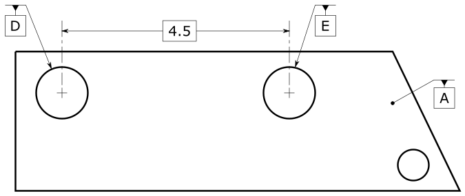
Another frequently-seen datum reference frame is the primary datum plane, followed by a secondary datum circle, followed by a tertiary datum width. Here's an illustration of the specification, where the primary datum plane is A, the secondary datum circle is D, and the tertiary datum width is E.

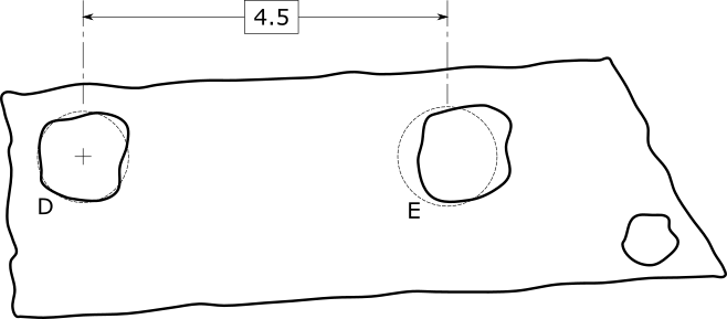
XactMeasure levels to the primary datum plane first, then it sets the origin on the secondary datum circle, and finally rotates the MEAS vector of the tertiary width to the THEO vector of the tertiary width. Here's an illustration of the XactMeasure behavior, using least squares math:

The geometric tolerance command with ASME and no datum modifiers gets a slightly different datum reference frame. The primary datum plane is fitted first. This yields a primary datum plane simulator and a planar invariant. The secondary datum circle is fitted next, oriented to the primary datum plane. This yields a secondary datum cylinder simulator and a revolute invariant. Finally, the tertiary datum width is fitted, oriented, and located to the higher precedence datums.
The tertiary datum width center-plane is coplanar with the secondary datum circle. That means the datum reference frame rotation angle is different than XactMeasure, even if the features all use least-squares math, and the geometric tolerance datum math option is LSQ.
Here's an illustration of the ASME geometric tolerance command behavior with no datum modifiers, showing the slightly different rotation angle:

If the specification is ASME and the tertiary datum has a translation modifier, or if the specification is ISO, then the vertical distance between the secondary and tertiary datum is unlocked. This means XactMeasure and the geometric tolerance command get the same datum reference frame when the features all use least-squares math and the geometric tolerance command math option is LSQ.
These examples show datum reference frames where it is relatively difficult to comply with the ASME standard, using XactMeasure (or legacy) dimensions when the tertiary datum does not have a translation modifier. In other words, the level-rotate-origin concepts made XactMeasure difficult to use. In these cases, you had to carefully best-fit a tertiary datum to the surface data, maintaining the correct nominal distances and orientations to the higher precedence datums. This process is difficult for most users.
These two examples are characteristic of the problems that can happen when you compare XactMeasure datum reference frames against a migrated geometric tolerance command datum reference frame. If you have this kind of problem during migration, you need to decide whether the XactMeasure behavior or the geometric tolerance behavior is correct for your application:
If the XactMeasure behavior is correct, that implies the drawing is incorrect in some way, because it needs a translation modifier or some other change. In that case, we suggest that you get the drawing changed and adjust the geometric tolerance command to have the translation modifier or whatever needs changing.
On the other hand, if the geometric tolerance command is correct but the XactMeasure behavior was incorrect, that means you used the XactMeasure command incorrectly for your chosen standard, because XactMeasure did not take the responsibility for interpreting the standard. This is in contrast to the geometric tolerance command, which does take responsibility for standards interpretation for most of the phases of evaluation for geometric tolerances. For more information, see "Introduction to Geometric Tolerances and Feature Control Frames" and "Structuring your Measurement Routine for Geometric Tolerances" in this chapter.
Projected tolerance zones are only allowed on auto cylinders. This is because the projected tolerance zone needs to start at the nominal end-face of the cylinder. Measured cylinders and constructed cylinders typically do not place the nominal start point at the nominal end-face. If you have a projected tolerance zone on a feature and that feature is not an auto cylinder, you need to change that feature type to be an auto cylinder. If you don't, the Migration Report states that projected tolerance zones are only allowed on auto cylinders, and the geometric tolerance command gives an error message that says that the feature type is invalid.
The three orientation tolerances are perpendicularity, parallelism, and angularity. The ASME Y14.5 standard does not define these orientation tolerances when there is a material modifier on a datum. The ISO 1101 family of standards is also incomplete for orientation tolerances with datums that have a material modifier. Therefore, the geometric tolerance command does not allow for datum material modifiers on orientation tolerances. If you have a material modifier on an orientation tolerance datum in XactMeasure, then during migration, a warning appears in the Migration Report that states that the material modifier on the datum has been removed.
The XactMeasure command allowed profile tolerances with no datums to have an OPTIMIZED_FIT math type. This math type has been improved on and superseded by the new min-max tolerance zone math type in the geometric tolerance command. Therefore, the OPTIMIZED_FIT math type migrates to the min-max tolerance zone math type (the DEFAULT math type). The Migration Report also lets you know that the tolerance zone math type was migrated to DEFAULT.
For position tolerances on spheres and surfaceless 3D points, the XactMeasure command allowed these zones: diametric, radial-arc, and perpendicular-to-radial. Unfortunately, on the diametric zones, XactMeasure did not allow you to specify the direction of the diametric zone. Meanwhile, the geometric tolerance command does not support radial-arc nor perpendicular-to-radial zones on spheres and surfaceless 3D points. In these cases, after migration to the geometric tolerance command, the tolerance zone is converted to a spherical zone shape, and a message saying so is displayed in the Migration Report.
XactMeasure supported some feature types that the geometric tolerance command does not support. This is because the geometric tolerance command strives to handle every feature type in the optimal way. When a feature type doesn't really make sense in a tolerance, it isn't allowed. XactMeasure, in contrast, treated all of the same feature types the same way. For example, XactMeasure treated surface points and intersection points the same way, even though they are fundamentally different and should be treated differently. If you have any XactMeasure tolerances on an unsupported feature type, after migration, the geometric tolerance command shows an error message that states that the feature is unsupported.
The geometric tolerance dialog box only allows features that make sense for the tolerance type. If you open the dialog box on a geometric tolerance that has one or more unsupported features, those features will be removed from the geometric tolerance command. At that point you can add back in features that do make sense for the tolerance type.
Sometimes a print that references ASME Y14.5 specifies position on a plane. However, this is not allowed per the standard. After migration, the position tolerance fails and shows an error message. To resolve this, you likely need to change the position tolerance to be a profile tolerance because that is allowed per ASME Y14.5. We recommend that you create a new geometric tolerance to represent this profile tolerance, and that you delete the position tolerance that gave the error.
XactMeasure allowed you to specify a material boundary size on ISO datums. Unfortunately, ISO 2692 : 2014 does not allow that. After migration to the geometric tolerance command, PC-DMIS removes the specified material boundary size from all ISO geometric tolerances. The migration report then shows a warning that states this removal.
XactMeasure circular runout tolerance commands had a toggle so you could choose between "axial" or "radial" tolerance zones on a circle. The "axial" toggle was for a circle that was measured on a planar surface. The "radial" toggle was for a circle that was measured normally.
The option to choose between these two zone types is not in the geometric tolerance command. This is because PC-DMIS no longer uses circles to measure a planar surface. This means all circle features have radial zones for circular runout. If your XactMeasure command had any axial zones on a circle, the Migration Report gives a warning and states that the axial zone on the circle was converted to radial.
If you need an axial zone, you can change the feature to be a plane with a circular point distribution. One way to do that is use an auto plane with an adaptive plane circle scan strategy.
XactMeasure could evaluate the position of irregular features. It did this with a so-called "boundary" method. The geometric tolerance command does not support this approach; you should use a profile tolerance instead. PC-DMIS migrates any XactMeasure commands with boundary-method position tolerances to profile of a line. In this case, a warning in the Migration Report states this change.
XactMeasure symmetry and concentricity tolerances under ASME Y14.5 migrate to the AXIS option. This makes the migrated results more similar to the XactMeasure behavior. If you prefer the MEDIAN_POINTS option instead, you can edit your symmetry and concentricity tolerances accordingly.
There is one exception: XactMeasure symmetry of one or two sets migrates to MEDIAN_POINTS because that is the behavior that is closer to the XactMeasure behavior.
With XactMeasure, you could set a planar zone direction that did not make sense for the considered feature. Such zone orientation vectors must always be perpendicular to the nominal axis vector of the feature, but XactMeasure did not enforce this.
By contrast, the geometric tolerance command enforces the perpendicularity. If your XactMeasure planar zone direction is not perpendicular to the nominal axis vector, the migration chooses a direction that is perpendicular, and shows a warning message in the Migration Report that asks you to check the zone orientation it chooses.
In rare cases, you may have an error in the geometric tolerance command after migration. For help with these messages, see "Troubleshooting Error Messages and Warnings".
As you can see in "Feature Types With and Without Surface Data", constructed best fit lines have a defined interpretation in the geometric tolerance command. Specifically, BFRE constructed lines are surface lines, and 2D constructed BF lines are surface lines. On the other hand, 3D constructed BF lines are surfaceless axes (unless they are constructed from points measured on a surface).
XactMeasure was inconsistent in how it treated constructed lines. In some cases, a 3D constructed BF line was treated as an axis, and in other cases, it was treated as a surface line. In those cases where XactMeasure treated the 3D constructed BF line as a surface line, the geometric tolerance command treats the BF line differently (as a surfaceless axis).
When this happens, you may want to change your 3D constructed BF line to be a 2D line so that the geometric tolerance command knows that the line feature is a surface line.
Suppose a datum reference frame is represented by a plane, line, and point, and that the line is a 3D constructed BF line.
Under XactMeasure, the line was treated as a surface line (controlling up to two degrees of freedom).
Under the geometric tolerance command, the line is treated as a surfaceless axis (controlling up to four degrees of freedom).
It is common in this scenario for the theoretical vector of the 3D constructed BF line to be non-parallel to the primary datum plane. Plane-axis datum reference frames control all six degrees of freedom when the plane and axis are neither parallel nor perpendicular, and that is what the geometric tolerance command does. The result is that the geometric tolerance command produces this error on the tertiary datum:
"Datum is invalid because it constrains no degrees of freedom."
In this case, the solution is to tell the geometric tolerance command that the secondary datum line is a surface line. You can do this by either (a) changing the secondary datum line to be a BFRE line, or (b) changing the secondary datum line to be 2D.
All constructed BFRE lines are surface lines. However, 3D constructed BFRE lines are somewhat difficult to use properly because their nominal workplanes are often not aligned with the drawing, even when you program your routine with a CAD model. This is particularly a problem when you use 3D constructed BFRE lines as a secondary datum. It is very common for the THEO line vector of these lines to be non-parallel to the primary datum plane. This means that the nominal workplane of the line is not parallel to the primary datum plane, and that the primary datum plane does not constrain the workplane of the secondary datum line. The result is this error message:
"Datum feature <feature name> is 2D. It needs a higher-precedence datum to constrain its workplane."
In such cases, the simplest solution is to change the 3D constructed BFRE line to be a 2D constructed BFRE line, so that the nominal workplane of the line is parallel to the primary datum plane.
XactMeasure used a Simultaneous Evaluation command to handle simultaneous tolerances. It unmarked the XactMeasure commands that belonged to it, so that the individual XactMeasure commands didn't execute and didn't do any reporting. Instead, when the Simultaneous Evaluation command was executed, all of the tolerances were evaluated and reported simultaneously.
The geometric tolerance command uses the new Simultaneous Tolerance command to handle simultaneous tolerances. It leaves the geometric tolerance commands marked, so that they execute and report separately. However, the evaluation is actually simultaneous. This new style allows for more intuitive and flexible reports, while it preserves the simultaneous evaluation of results.
During migration, PC-DMIS migrates XactMeasure commands to geometric tolerance commands. It also migrates the Simultaneous Evaluation command to the Simultaneous Tolerance command, and the geometric tolerance commands are marked for execution. For more information, see "Simultaneous Tolerances".
If a set of profile of a line tolerances are part of a simultaneous evaluation command, and if those profile of a line tolerances do not reference any datums, then those profile of a line tolerances reference a workplane. Unfortunately, implicit datums (workplanes) are not supported by the simultaneous tolerance command. The workplane references are deleted upon migration. You will need to construct an explicit datum for the profile of a line tolerances.
There are many types of outputs from an XactMeasure dimension that PC-DMIS can migrate to the geometric tolerance command. These outputs are statistics output, expressions on the XactMeasure dimension, Excel output, basic scripting, automation, and report modifications.
Some of these outputs mostly work after migration, such as statistics, expressions, Excel output, and report modifications. The geometric tolerance command has many more output capabilities than XactMeasure did, so you may wish to augment how you use these outputs after migration. Due to the capabilities upgrade, not all of these outputs behave exactly the same way after migration. Be sure to check your measurement routines to ensure that the migration worked for you.
Basic scripting and automation mostly do not work after migration. This is because they depend on the internal workings of the commands that they operated on. The geometric tolerance command on the inside, is almost completely different from the XactMeasure command. This means most basic scripting and automation needs to be rewritten for the geometric tolerance command.
More:
Options to Control Migration Math Types and Standards
Migration to Multiple Segments
Migration to Constructed Input Features