While this calibration process is specific to the TESASTAR-R / HR-R Probe Changer, it is similar to the steps required for any probe changer that PC-DMIS supports.
This documentation expects that you are positioning the probe changer so that the center post of the probe changer is vertical to the CMM table with the ports parallel to the CMM table:

TESASTAR-R / HR-R Probe Changer
This probe changer MUST be mounted on the machine table parallel to a machine axis, such as the X or Y axis. For mounting instructions, consult the documentation that came with your probe changer.
You should mount all HD ports on the end of the tool changer rack. If you would like to mount the HD ports in the middle of the rack, you must set the UseTCVerticalClearanceForHD_TESASTAR-R entry to True in the PC-DMIS Settings Editor. This will allow the wrist to move up during tool changes to avoid the HD ports. For more information, see the PC-DMIS Settings Editor documentation.
Probe Changer Components

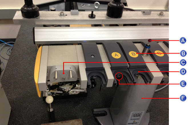
TESASTAR-R / HR-R Probe Changer components:
A - Datum Sphere
B - Lid/Cover
C - HD Port
D - Port
E - Key
F - Center Post
Wrist Types
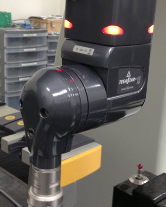
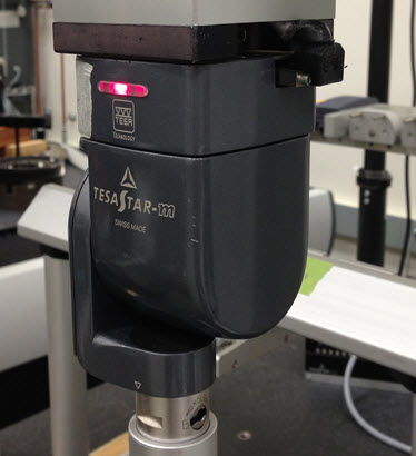
The procedure for calibrating the TESASTAR-R / HR-R Probe Changer varies depending on the type of wrist. This documentation defines the wrists as follows:
HD wrist with an HDKJ extension:

Wrist:

Calibration
To calibrate your probe changer:
Step 1 - Select the TESASTAR-R / HR-R Probe Changer
Step 2 - Define the Communications Port
Step 3 - Define the Mount Point and Wrist Angle
Step 5 - Prepare for Calibration
Step 6 - Take the First Manual Hit
Step 7 - Take the Second Manual Hit
Step 8 - Take the Probe Hit on the Datum Sphere