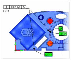
PC-DMIS lets you insert valuable dimensioning information in the form of Feature Control Frames (FCFs) into your measurement routine. FCFs are special rectangular boxes that house standard GD&T (Geometric Dimensioning and Tolerancing) symbols and information. When you insert an FCF into the Edit window, PC-DMIS also draws the actual frame in the Graphic Display window.

Sample Feature Control Frame (see FCF1)
To insert an FCF command, access the Insert
| Dimension submenu, ensure that the Use Legacy
Dimensions menu item is not selected,
and then select the appropriate dimension. PC-DMIS
displays the XactMeasure GD&T dialog box
for that dimension. Once you create the FCF, PC-DMIS
inserts it along with dimension information into the measurement routine.
FCFs provide you with a new way of dimensioning your part. All of the same options you had with the previous legacy Dimensioning functionality still exist with FCFs (see the information on the XactMeasure GD&T dialog box later in this chapter). If you prefer the old way of doing dimensions, however, select the Use Legacy Dimensions menu item. For information on legacy dimensions, see the "Using Legacy Dimensions" chapter
Also, since the Location, Distance, Angle, and Keyin dimensions are not part of the ASME and ISO standards, they are always created using legacy dimensions, even if you deselected the Use Legacy Dimensions menu item.
This chapter covers the following topics: