
The To Points function is available for auto contact features of type Plane, Circle, and Cylinder.
If you select the To Points icon on the Auto feature bar, PC-DMIS creates the feature as individual Vector Points with the associated shape constructions. PC-DMIS uses the hits of the Auto feature to obtain the Vector Points.
PC-DMIS applies the Best Fit Recompensate algorithm to the Vector Points to compute the constructed feature. Following is an example for a Circle feature:
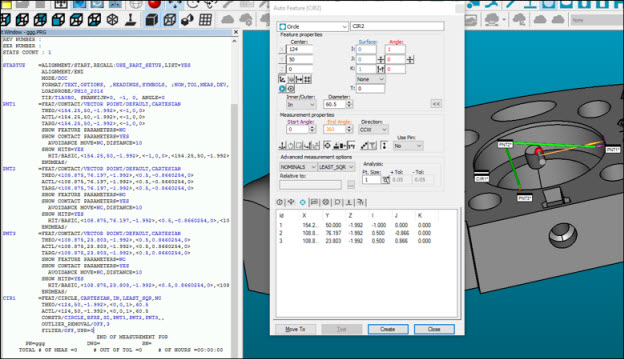
Example of a circle feature generated with To Points icon enabled
For more information about the Best Fit Recompensate algorithm, see the "Constructing a Best Fit or Best Fit Recompensate Circle" topic.
If the Void Detection function is enabled for the Auto feature, or if you drag the hits (user-defined hits), the resulting Vector Points will take care of it. For example:
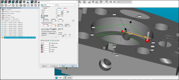
Example of a cylinder generated with Void Detection and To Points functions enabled
The To Points function also works with QuickFeatures. It is feature-type dependent. For example, you can enable the icon for circle features and disable it for cylinder and plane features.
After you create the measurement routine, the "optimize path" task can be used to assign the probe head orientation and to re-order the vector points. This feature enables PC-DMIS to measure all of the points with the same tip in one step even if they belong to different features. For more information about path optimization, see the "Optimizing the Path" topic.
PC-DMIS ignores some Auto feature measurement options (such as auto wrist, circular moves, clearance plane, and sample hits).
PC-DMIS moves some of the measurement options from the original Auto feature to the resulting Vector Points (such as the coordinate types and the thickness).
The Test button is unavailable if the To Points option is enabled.