Configure the Kinematic and Axis Information
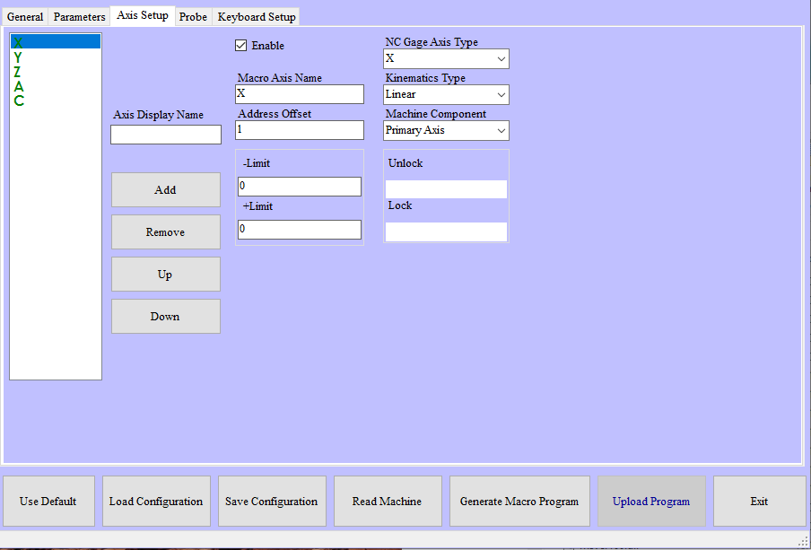
NC Gage Axis Setup tab
Required Parameters | |
|---|---|
Step | Instructions |
1 | Verify that all axes required for measurement are listed in the available axis list
|
2 | Verify that all axes required for measurement are displayed in GREEN
|
3 | Verify the properties of the primary linear axes (X, Y & Z Axes, not extended linear axes)
|
4 | Verify the properties of the rotary axes
|
For rotary tables / Lathe Spindles:
| |
Additional Notes | |
|---|---|
Item | Notes |
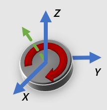
Rotation Vector | The rotation vector (I, J, K) describes the direction of the axis of rotation for a rotary axis. I, J, and K are the components (direction cosines) of the vector in the X, Y and Z directions respectively. The examples below illustrate this. |
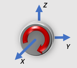 Rotary axis rotates around the X-Axis (I=1, J=0, K=0)
| |
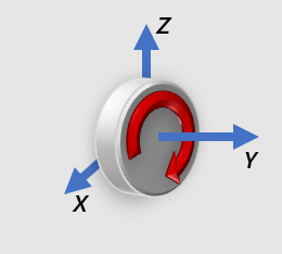 Rotary axis rotates around the Y-Axis (I=0, J=1, K=0)
| |
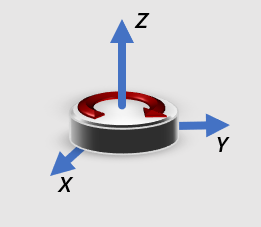 Rotary axis rotates around the Z-Axis (I=0, J=0, K=1)
| |
 Rotary axis is inclined (I=0.7071, J=0, K=0.7071)
| |
Clockwise | Clockwise or counter clockwise is determined by looking down the axis of rotation and is the direction of positive rotation. In each of the examples above, the clockwise direction is shown with the red arrow |
Upper / Lower | If a machine is equipped with trunnion tables, the relationship of the two tables to each other must be specified.
|