Machine Definition - Probe Tab
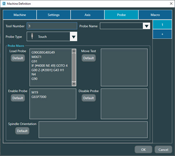
The following information provides a brief description of each section of the Probe tab on the Machine Definition dialog box.
Notice
For details on advanced features, please contact Hexagon Technical Support: https://support.hexagonmi.com/s/
Tool Number - Type in a new value or accept the current value. This is an integer value to indicate where the CNC can find the physical probe.
Probe Name - This is the name of the probe as defined and used by PC-DMIS to perform the actual measurements. This completes the mapping between the CNC using the Tool Number value and PC-DMIS using the Probe Name value.
Probe Type - Select the type of sensor for your system. You can select either a Touch or Laser sensor from the list. If you select Laser from the Probe Type list, NC Server shows the Scanned Data area. For details on the Scanned Data area, see "Machine Definition - Probe Tab - Scanned Data Area" topic.
Important
For Siemens controllers, the top options are slightly different.
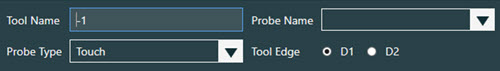
Tool Name - See description for Tool Number above.
Probe Name - See description above.
Probe Type - See description above.
Tool Edge - Select this option to measure with NC Server. Define the tool edge as the length of the tool to the center of the stylus tip.
Note that if you typically use measuring cycles from the machine probe builder or the probe's manufacturer, the probe length may already be defined in D1, but this length will typically be to the end of the stylus. In this case, select D2 in NC Server and define D2 on the controller to be the tool length to the center of the stylus tip. If you do not use other measurement cycles or if D1 has already been configured as the tool length to the center of the stylus tip, then select D1.
Probe Macro area
Load Probe - This area defines the macro that NC Server uses to load the probe from the probe changer.
Enable Probe - This area defines the macro that NC Server uses to turn the probe on.
Move Test - This area defines the macro that NC Server uses to move the probe 1 micron to ensure the probe is on.
Disable Probe - This area defines the macro that NC Server uses to turn the probe off.
Spindle Orientation - This area defines the macro to rotate the probe in the PC-DMIS C-axis.
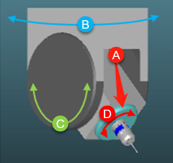
This red arrow points to the spindle.
This is the base rotary axis, which means that when it rotates, the C-axis orientation rotates with it. The base rotary axis is the B-axis that you define in the PC-DMIS Probe Utility dialog box when you select your tips.
This is the secondary rotary axis and corresponds to the A-axis that you define in the PC-DMIS Probe Utility dialog box when you select your tips.
This is the spindle's axis.
Machine Definition - Probe Tab - Scanned Data Area
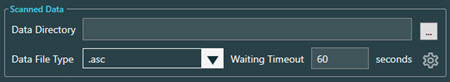
If you select the Laser option from the Probe Type list, NC Server displays the Scanned Data area which contains these options:
Data Directory - This defines the location that NC Server searches for the scanned data file, for example, a .asc file type.
Data File Type - Select from the list the appropriate file extension. NC Server uses this as the type of file to search for in the location defined in the Data Directory box.
Waiting Timeout - The value you type in this box defines the maximum number in seconds that NC Server waits to receive scanned data.
 Update Laser Probe Center button - Click this button to open the Update Laser Probe Center dialog box.
Update Laser Probe Center
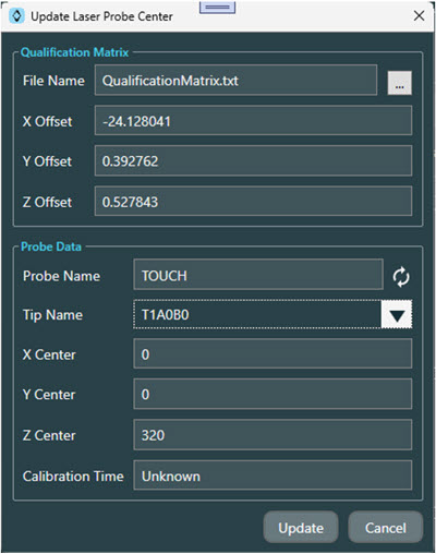
You can use this dialog box to read in the offset values from the qualification matrix generated by the NC Measure application and update the offset values to the center of the selected probe and tip.
The options in the Qualification Matrix area of this dialog box are:
File Name - The File Name box shows the current file that NC Server used to read in the qualification matrix data. You can click the Browse button (
 ) to display a Browse for Folder dialog box to navigate to and select the appropriate qualification matrix file.
X Offset - Upon successful import of the qualification matrix data file, this text box shows the X offset value read in from the file.
Y Offset - Upon successful import of the qualification matrix data file, this text box shows the Y offset value read in from the file.
Z Offset - Upon successful import of the qualification matrix data file, this text box shows the Z offset value read in from the file.
The options in the Probe Data area of this dialog box are:
Probe Name - This box shows the name of the selected probe.
 Load Probe Data button - Click this button to load the probe data of the selected probe.
Tip Name - If the probe data loaded successfully, you can use the drop-down arrow to display a list of all the tip names for the selected probe.
X Center - This box shows the X value for the center of the selected tip.
Y Center - This box shows the Y value for the center of the selected tip.
Z Center - This box shows the Z value for the center of the selected tip.
Calibration Time - This box shows the calibration time of the selected tip.
 Update button - Click this button to update the X, Y, and Z offset values from the qualification matrix file to the center of the selected tip.